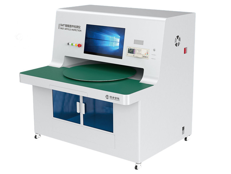
It can detect first piece boards of various types, such as solder paste boards (printed solder paste with components attached), adhesive paper boards (double-sided adhesive with components attached), and red adhesive boards (printed red adhesive with components attached). The detection types cover material errors such as BOM quantity errors, repeated positions, XY coordinate missing definitions, and multiple definitions, as well as process issues such as multiple, missing, wrong, reverse, flip, and rotation of circuit boards. It also includes electrical performance of components such as resistors, capacitors, inductors, and diodes (usually due to incoming material errors).
The core hardware of JD-FAI includes a computer, LCR bridge, and high-definition scanner. By integrating self-developed software systems, the three are perfectly combined. In addition to achieving fast and accurate measurement functions for resistance, capacitance, and inductance, it can also automatically inspect the appearance of printed components such as IC chips and transistors.
Functional Features
Compatible with various BOM tables
The software system independently developed by Jiedeng has a powerful and flexible BOM table parsing function, which can define different parsing rules for different customers' BOM tables, thus being compatible with various BOM tables.
Adopting the optimal path detection algorithm
Automatically screen the optimal path for the customer during testing, mark it with a dashed line in the circuit diagram on the display, and use voice prompts to greatly improve detection efficiency.
Dual image mode
It has a dual image mode, where both the physical image and the tag image can be displayed simultaneously. Easy to compare and view during testing.
Automatically determine the detection results
The system receives high-definition images from the scanner and detection data from the digital bridge, automatically determines PASS (correct) or FALL (incorrect), and can also manually determine PASS on the computer.
Screen printing, automatic recognition and judgment of direction and polarity
The system can use visual comparison techniques similar to AOI to automatically compare IC chips, diodes, transistors, resistors, capacitors, and other components containing characters. Support multi-point detection of the same component, and the programming process is simple and fast. The program can be written once and reused multiple times.
Sampling inspection or material replacement sampling testing
The sampling function by station can be used for sampling and testing based on the station table, BOM table, or midway material replacement.
Drawing design auxiliary function
The system can color and mark drawings, including tag numbers, standard values, precision, and specifications.
Turn on the LED and measure the polarity of the diode
The software, combined with LCR's unique voltage testing function, can light up the LED and measure the voltage across the diode to determine if its polarity is correct.
Automatically generate reports
After the test is completed, a test report will be automatically generated, which can be exported in Excel/PDF format to meet the customer's circulation needs.
ERP and MES integration function
The report can be integrated with the customer's EPS/MES system and uploaded on a computer.
Flexible definition of user permissions
Each operator can establish an account and flexibly define user permissions to avoid malicious deletion, modification, or misoperation.
Bulk material testing
Configure independent bulk material testing software, which can control the bridge through the PC end when measuring bulk materials, such as switching test gears and frequencies, and display real-time test values on the PC screen. Bridge zero foundation employees can directly use the bridge without the need for manual measurement through various buttons on the bridge.
Technical Parameter
Computer configuration: I7 industrial control
Monitor size: 24 inches
Test frequency: 20Hz-300KHz
Test accuracy: 0.05%
Image capture method: High definition industrial camera
Automatic Visual Inspection: Supports
PCB size range: 600 * 550mm (customizable for larger sizes)
PCB upper and lower component height limit: upper surface: 35mm, lower surface: 50mm
Power supply: AC220 ± 20V 50/60Hz
Language: Chinese/English
Equipment weight: approximately 300KG
Dimensions (W * D * H): 1350mm x 1250mm x 1350mm
Please leave a message below before downloading the materials. Thank you.